

Typical operational survey altitude is 5 - 50 m above ground level for mineral exploration and geological surveys. For UXO or underground object detection the survey altitude can often be even lower.
Modern magnetometer systems come in different configurations:
- Foldable arm systems (SPH Engineering MagNIMBUS, SENSYS MagDrone R1)
- Leg-mounted sensors (SENSYS MagDrone R3/R4)
- Aerodynamically shaped sensors on suspension ropes (Geometrics MagArrow)
- Cable-suspended sensors (GEM Systems GSMP-35U/25U, GEODEVICE AeroSmartMag/AeroQuantumMag)
Each design behaves differently during flight, turns, and speed changes. Understanding these differences is important for planning missions that produce clean and usable data.
Preparing the map and elevation
Terrain elevation models (DEM / DTM) for magnetic survey planning
One of the first steps to planning magnetic surveys is choosing which terrain model to use. UgCS drone survey software comes out-of-the-box with SRTM 1 Arc-second terrain elevation data (30 m resolution) available worldwide. In the USA and Alaska USGS ⅓ Arc-second terrain elevation data with 10 m resolution is available.
Depending on the area where the surveys are done and the terrain elevation changes, operators should choose whether to use existing default elevation data or use higher accuracy DEM. UgCS allows import of large high-resolution digital elevation models (DEM) from GeoTIFF (.tif) files. DEMs up to 1 meter resolution can be used with unrestricted size. In comparison, software like DJI Pilot 2 restricts the maximum size of DEM that users can import.
The DEM elevation data of various geographical locations can be outdated or imprecise. This is particularly true for distant and rural areas, where the majority of magnetic surveys are conducted.
There are many sources of precise DEM data, some of which are freely available, like the ArcticDEM, and some of which are expensive commercial products, like the Airbus WorldDEM.
Digital Surface Models (DSM)
In addition to normal DEM / DTM models, UgCS also allows the import of digital surface models (DSM). While digital terrain models (DTM) typically contain only information about the terrain elevation, surface models, on the other hand, include information about everything on the surface. Typically this means vegetation and buildings are included.
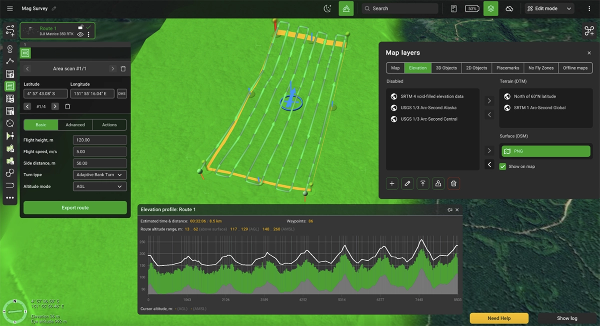
All of this is managed through the Map Layers window Elevation tab in UgCS.
Important note here is that DSMs are used for preview and not flight planning. This makes it possible to import LiDAR DSM data to ensure that over large forested areas the magnetic surveys can be executed safely.
Map Overlays
The map can be just as important. Users have the option of choosing between using default base map layers (Google, Bing) or using other publicly available online map sources. In certain situations when flying low-altitude surveys pilots can also choose to use their own high-resolution maps imported into UgCS. This can help identify obstacles and plan flights according to real-life situations instead of outdated satellite imagery. Visually it can help identify:
- Vegetation that may not appear fully in satellite map
- Buildings, powerlines or other obstacles
- Terrain features and water bodies
- Potential landing zones
Offline maps
Magnetic surveys are often done in areas of limited mobile network availability or even areas with no cellular coverage. This makes the ability to use the system fully offline mission-critical.
UgCS allows caching of maps and elevation for offline use. Regions can be up to 100 square kilometers in size each. This feature, combined with the fact that UgCS installs locally on the PC, makes it possible to use it fully offline.
Guide to Magnetic Survey Flight Planning in UgCS
Note: The following section showcases the upcoming features of UgCS 6.0 which is set to release in H1 of 2026.
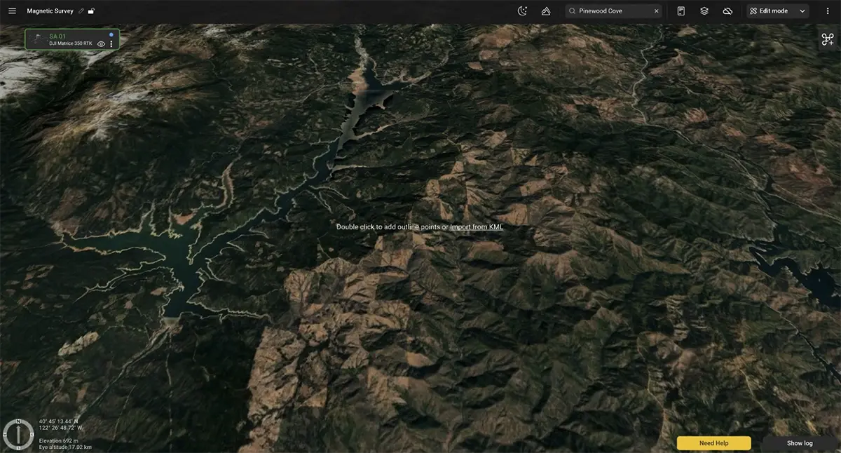
Planning the Survey Area
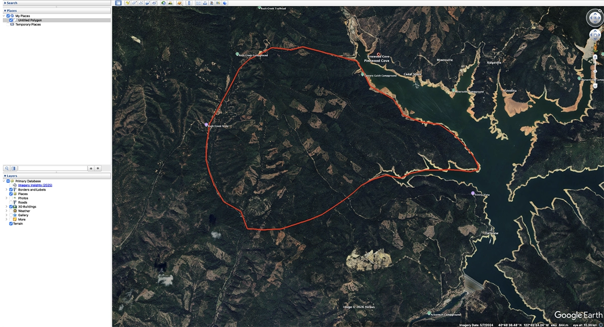
Survey clients typically provide boundary files in KML format, which UgCS allows to import directly to define the magnetometer survey area. For magnetic surveys these can also be KML lines of previous magnetic survey lines done in the same area.
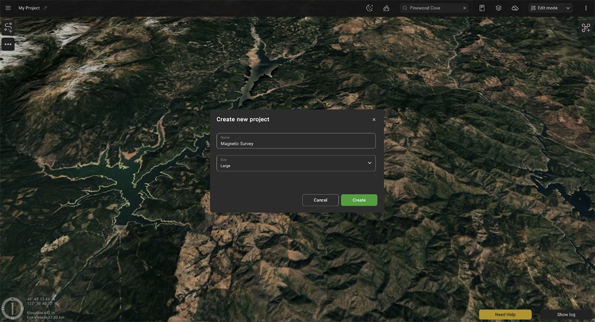
The next step is to create a large area project in UgCS.
Compatible Drone Platforms for magnetometer surveys
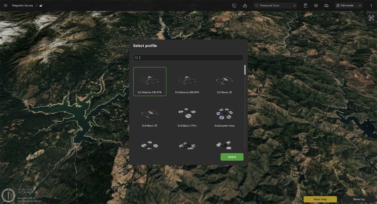
UgCS supports mission planning for the most popular drone platforms used in magnetometer surveys, including:
- DJI Matrice 400 - newest generation of DJI Enterprise drones
- DJI M350 RTK - newer generation with improved weather resistance
- DJI M300 RTK - robust and proven workhorse
Beyond DJI platforms, UgCS is compatible with ArduPilot and PX4-based systems such as:
- Inspired Flight - IF800, IF1200A
- Harris Aerial
- Freefly Alta X
- And more …
This compatibility gives geophysicists and survey operators flexibility in choosing the right platform for specific mission requirements and terrain conditions.
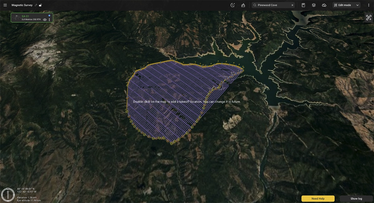
After the desired drone platform is selected, it is now possible to either draw the project boundary on the map or import it from a KML file. In this case we will select it from a KML file.
Once the initial boundary has been created / imported, add at least one takeoff location. This can be changed later.
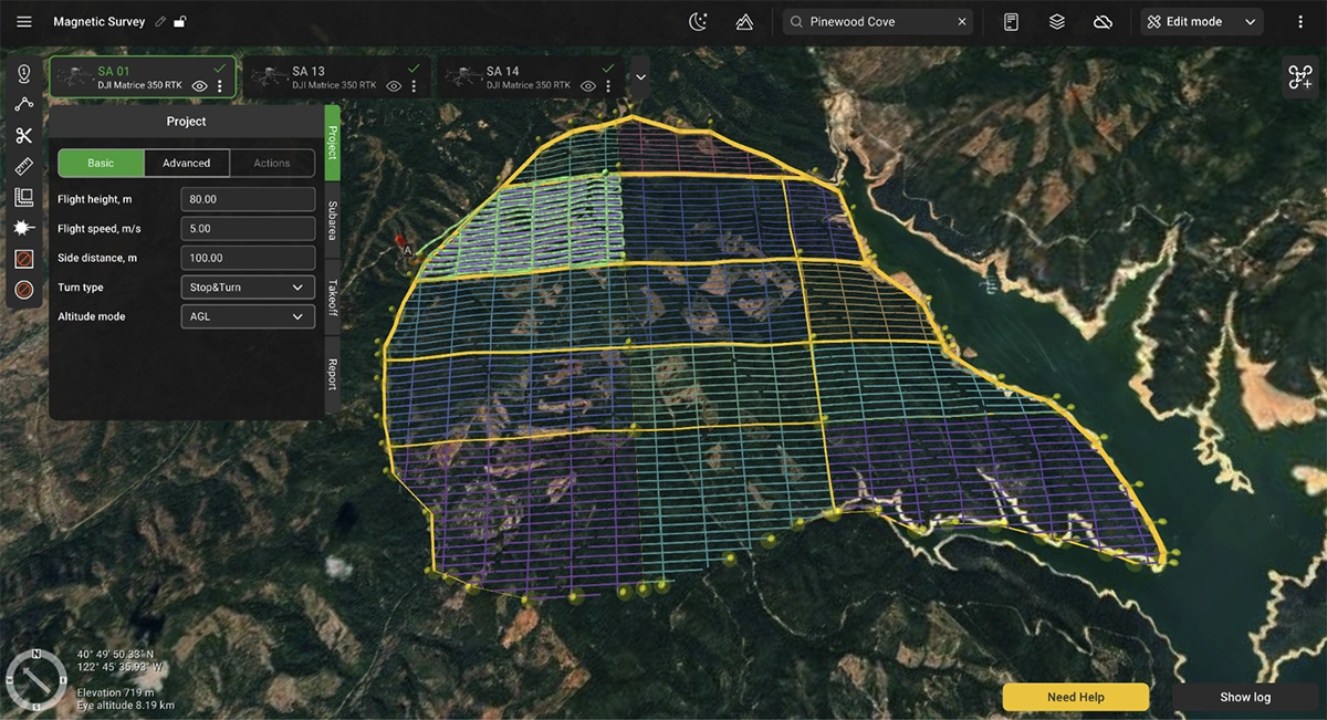
Splitting large survey areas into Sub-Areas
Large survey areas often cannot be completed in a single flight due to battery limitations. UgCS provides tools for dividing survey areas into manageable sub-areas that can be flown sequentially.
Cut lines can be used to split the large project into smaller sub-areas.
When planning multi-flight missions:
- Each sub-area should be sized according to expected flight time with safety margins
- Overlap between adjacent sub-areas ensures data continuity
- Sub-areas can be organized to minimize repositioning between flights, allowing to cover an entire sub-area from a single take-off position
- Battery swap locations can be planned strategically
Each sub-area takes the main flight parameters from the project settings. The key parameters are - flight speed, flight altitude / height, and side distance.
- Flight speed: depends on survey goals and sensor sampling rate. Modern magnetometers like the MagNIMBUS, SENSYS MagDrone series, and MagArrow have sampling rates in the hundreds of hertz, allowing safe speeds up to 10m/s for multirotor platforms for any survey type. However, older sensors operating at 10-20 Hz may limit speeds if the goal is detecting small anomalies. For very low-altitude UXO surveys, safety considerations often determine maximum reasonable speed, sometimes 3-4m/s regardless of sensor capabilities.
- Line spacing varies significantly based on survey objectives, ranging from 0.5m intervals for detailed UXO work to 200m for regional geological reconnaissance.
- Flight altitude depends on survey type and client specifications. UXO detection surveys might require 1m or even lower clearance between sensor and surface, while mineral prospecting usually typically calls for something between 10 to 50 m. Minimum safe altitude must account for obstacles, vegetation, and the drone's ability to maintain precise altitude control over changing terrain.
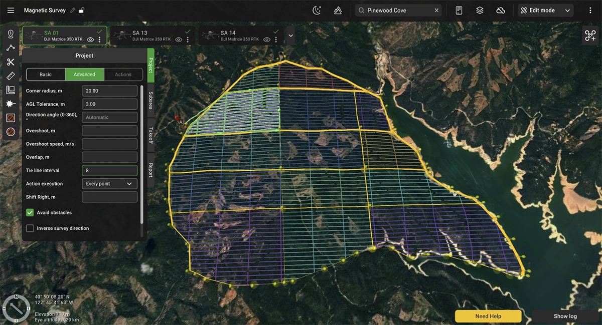
The 'AGL tolerance' parameter allows users to specify how precisely the UAV should follow the desired altitude above ground.
There is a trade-off between following the precise altitude in a certain range and the number of generated waypoints.
The following more precise altitude allows for a safer flight and better quality data. On the other hand, every autopilot has a predefined limit on the number of waypoints that it can handle at once. For example, the DJI M600 drone can only accept 99 waypoints during a single flight.
If a route consists of more than 99 waypoints, intermediate landings are needed to upload the next array of waypoints. (In theory, DJI’s autopilots are able to upload a new route while the aircraft is still in the air, but this operation is less safe and thus should be used with caution.)
For example, if the AGL altitude is set at 40m with a 1m altitude tolerance, UgCS will generate hundreds of waypoints to keep the drone's altitude in the vertical altitude tolerance corridor between 39m and 41m. The smaller the altitude tolerance value, the more waypoints will be generated. Therefore, altitude tolerance must be set to a value that would not lead to exceeding the maximum amount of possible waypoints permission. As a practical example, increasing the altitude tolerance from 1 m to 10 m reduced the waypoint count from 872 to 364 for the same route, cutting the required number of flights from nine to four on a DJI M600.
Configuring tie lines for magnetic data leveling
A crucial component of drone magnetic surveys are the tie lines. They allow to assess data consistency across the survey area and to apply a technique called “tie line leveling” for collected magnetic data. Tie lines are typically flown perpendicular to main survey lines and are spaced further apart.
Moreover, tie lines should be consistent across the whole survey grid, meaning that their position should not change across the whole survey area. This is exactly what UgCS allows to do.
Tie lines parameter in project settings allows to choose the frequency of tie lines. For example:
0 - no tie lines
1 - one tie line per every one survey line
5 - one tie line per every 5 survey lines
Adding take-off points, optimizing flight time
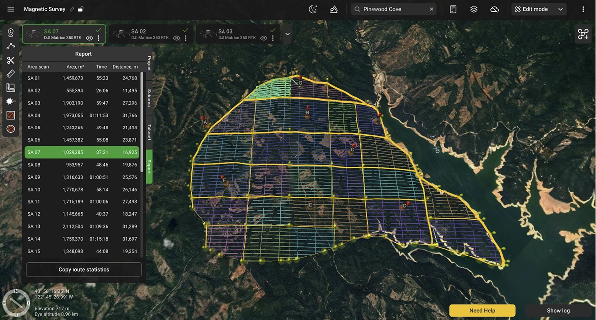
The Report section allows to preview the estimated flight time of all sub-areas. Using it is possible to make adjustments to the area size and parameters before heading into the field. It makes it possible to plan the sub-areas in such a way that allows to optimize the flight time of each sub area for the drone platform used, ensuring each area can be flown with a single set of batteries.
Strategic placement of take-off points is important not just for mission safety but also efficiency. Planning and setting take-off positions well allows to minimize time required to cover each area.
Too many take-off points will mean having to move equipment around multiple times. Too few take-off points will increase time needed to cover each area. So optimisation here is very crucial.
Route safety parameters
Most parameters in this window are very important for the mission’s safety. Therefore, we shall consider each parameter in detail:
- Take-off point altitude above ground: In most cases, this field should be left empty, except in situations like when starting the flight from the roof of a building. In that case, you need to enter the elevation of the actual take-off point above ground level to accurately calculate the altitudes for each waypoint of the route.
- Maximum altitude above ground: In most countries, there is a legal limit for the altitude above ground (AGL) for drone flights, unless the operator has special permission. Typically, 120m (or 400ft) is the most common limit. Please don’t set this parameter at higher values without permission from your country’s authorities. This setting can be changed in some instances when the drone has to fly higher than 120m from the home location but not more than 120m above ground level.
- Return home altitude: If something goes wrong with the equipment (low battery condition, RC signal loss - depending on drone type and settings), or if the operator presses the ‘Home’ button on the remote controller, the drone will ascend to this altitude before flying back to the home location. One must keep in mind that the return altitude is calculated relative to the home (take-off) position, rather than its current position where the return-to-home sequence was initiated. As a general rule, this parameter’s value should be above the height of the tallest obstacle (including natural obstacles like trees, hills, and rocks) in your survey area.
- Trajectory type: For terrain-following missions, this parameter should be set to ‘Straight’. Please note that in this mode your drone will fly between waypoints in a straight line, so the altitude above ground should exceed the height of all trees and other obstacles in your survey area.
- Action on the loss of RC: This parameter defines what should happen if the communication link between the ground station (RC remote controller) and your drone is lost. By default (option ‘Home’), the drone will abort the mission, ascend to the Return home altitude and return to the Home location. Another option for this parameter is ‘Continue’. We strongly advise always use the default option (‘Home’). Firstly, in most countries, the law mandates that a permanent communication link should be maintained between the drone and the operator throughout the flight. Secondly, if something goes wrong (really wrong) after the communication link has been lost, you may never find your drone because the ground station will display only its last known position. Naturally, there are some instances in which maintaining a constant radio link is nearly impossible, but overall you should think twice before selecting the ‘Continue’ option.
In addition, please note that if the ‘Continue’ option is selected, the drone will fly to the last waypoint and hover there. If the radio link is lost, the drone will hover until its batteries are drained, at which point it will most probably (depending on the drone’s settings) land at the last waypoint. Consequently, the last waypoint of the route should always be placed near the desired landing point.
Setting an optimal direction angle of survey lines
UgCS allows users to change the direction of survey lines by entering the value in the project settings or dragging the direction indicator on the map.
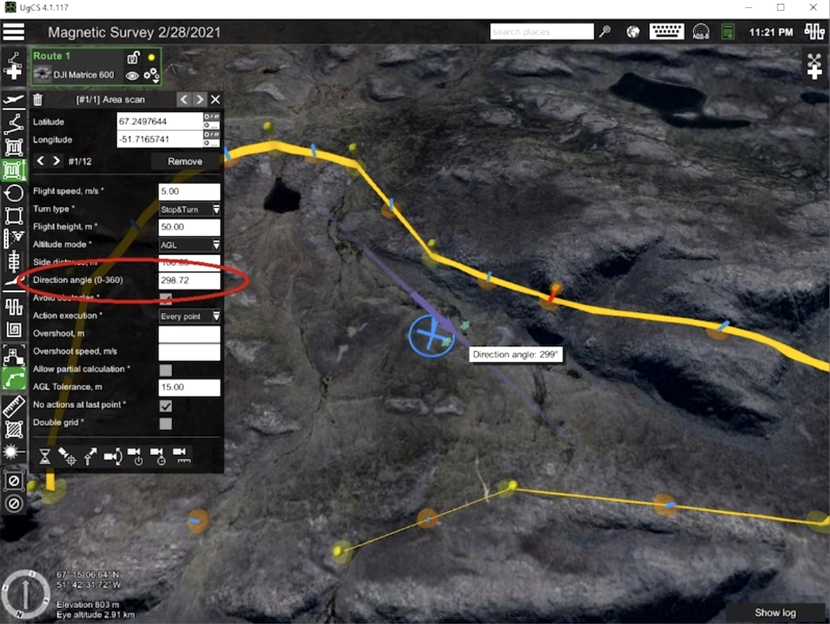
The survey lines can be aligned parallel to the survey area boundaries in order to reduce the duration of the flight and to minimize the number of waypoints and turns. For instance, in the example below we can get a much more optimal route by setting the direction angle to 261 degrees:
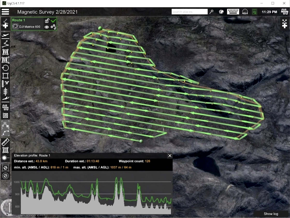
A general rule is that to minimize flight time you need to set the direction of survey lines parallel to the longest side of the ‘Area scan’ boundary.
But the selection of the direction of the survey lines may be a more complex process. In the case of non-convex polygons, you may need to minimize fly-outs outside of the survey area. Also, to gather high-quality magnetic data, you need to choose the direction so that, when on survey lines, the drone will not have to make energetic vertical maneuvers for terrain following. Ideally, when possible, the drone should keep more or less the same absolute altitude on the survey lines. Moreover, for mineral exploration purposes, the line direction would be determined by the exploration manager or geologist on-site and will be independent of survey size or shape.
Adding overlap and overshoot
Key part of magnetic surveys is ensuring optimal data coverage across the boundaries of different areas. Data quality often drops significantly during cornering.
UgCS allows adding overlap and overshoot to the whole project. This makes it possible to cut out the corners of each survey area, leaving only good consistent magnetic data.
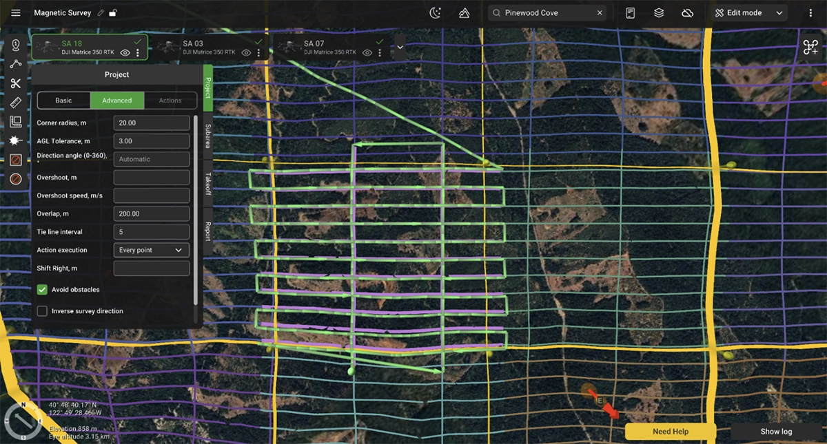
Overshoot segments are added at the ends of survey lines and also allow control of the vehicle speed, making it corner slower. This is important for suspended sensors such as the Geometrics Magarrow, GEM GSMP and GEODEVICE magnetometers.
Overlap, on the other hand, increases the size of the whole area in all directions.
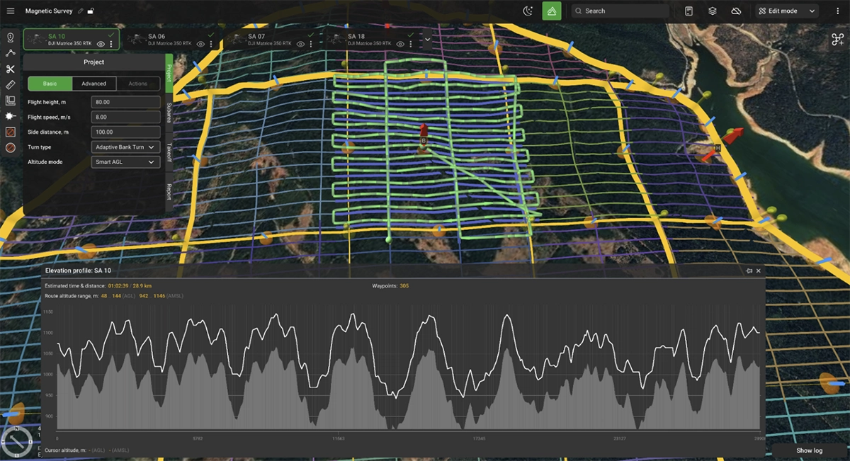
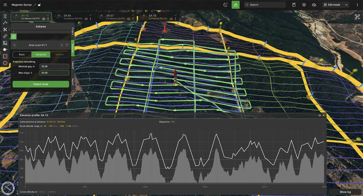
Trajectory Smoothing for Magnetic Surveys
UgCS includes a Trajectory Smoothing algorithm specifically designed to improve flight paths for geophysical surveys. This feature is particularly valuable for magnetic surveys conducted over terrain with steep elevation changes.
The algorithm provides two customizable settings:
- Max Slope - limits vertical angles for smoother flight trajectories
- Minimal Gap - avoids sudden dips or sharp inclines
These settings protect sensitive sensors like magnetometers from excessive movement while optimizing battery consumption. When surveying mountainous or hilly terrain, trajectory smoothing prevents the drone from following every minor terrain variation, instead creating a flight path that balances terrain following with operational efficiency.
For magnetic surveys, this means:
- Reduced sensor motion artifacts in collected data
- Extended flight times through more efficient power management
- Smoother, more predictable flight characteristics
Elevation profile before trajectory smoothing is applied:
Elevation profile after trajectory smoothing is applied:
Uploading and Syncing Routes to the Drone
Once the whole project is planned, it is time to go fly. There are different ways to go about this based on the drone used.
For DJI drones here are the options:
- Use UgCS Cloud function, allowing flight plans to be synced up to the remote controller over internet
- Use direct connection from Pilot 2 app to UgCS over local Wi-Fi. This allows to sync route library to Pilot 2 app and view drone telemetry in real time in UgCS.
- Use UgCS Companion app. It makes it possible to control the drone directly from UgCS or launch one of the pre-synced routes.
For ArduPilot / PX4 - based systems:
- Connect the drone to UgCS via USB radio link
- Connect the drone to UgCS via Herelink (or similar) controller. Upload the route and monitor progress in QGC app on the controller. We also suggest reading our guide on using ArduPilot and PX4 drones with UgCS.
In case flight planning is done remotely, flight plans can also be exported from UgCS and sent to drone operators in the field.
Sensor-Specific Settings for Drone Magnetometers

SPH Engineering MagNIMBUS, SENSYS MagDrone R1
These magnetometers with foldable arm design provide good magnetometer sensor stability and allow extreme low sensor to ground clearance. Design assumes probability to touch the ground or obstacle on survey lines without drone crash. That makes these sensors especially effective for UXO search over fields with vegetation.
Recommended settings:
- Flight speed depends on altitude and roughness of terrain only. For extremely low altitudes over flat farm fields it can be in the range 4…8 m/s, for rough terrain it can be as low as 1m/s.
- Flight altitude when the True Terrain Following system is used can be selected to have sensor elevation over the ground the same as height of vegetation without additional safety margin. BUT please don’t plan the mission in the way to have sensors regularly touch the ground or hard obstacles.
- Drone should fly with nose pointing to the next waypoint, please don’t fix the absolute heading for survey grids.
- Recommended Overshoot segment length is equal to 2x flight speed (e.g., 10m for 5m/s), with 2x times reduced speed.
- For dense survey grids (with spacing 1 m or less) use Stop&Turn turn types for better accuracy of survey lines.
Geometrics MagArrow
The MagArrow's aerodynamic design and 3m suspension ropes provide excellent magnetic noise isolation but require careful planning for turns. The sensor is prone to pendulum motion at turn points.
Recommended settings:
- Overshoot segments: 40-80m for 8m/s flight speed (5-10x speed in meters)
- Reduced overshoot speed: 4m/s (roughly half the survey line speed)
- If tight line spacing (1-10m) is used, the sensor can also oscillate horizontally during U-turns
- Use Adaptive bank turns.
Ghost anomalies in magnetic data that appear at equal distances from survey line starts indicate insufficient stabilization. Longer overshoots with reduced speed eliminate these artifacts.

SENSYS MagDrone R3/R4
These leg-mounted or hull-mounted sensors offer greater stability during turns compared to suspended systems. The rigid mounting reduces pendulum effects.
Key requirements:
- Ensure sensor bar remains perpendicular to flight direction
- Overshoots can be shorter: 5-10 m is typically sufficient
- For dense survey grids (with spacing 1m or less) use Stop&Turn turn types for better accuracy of survey lines.
The more stable mounting allows for somewhat tighter turn radii and less conservative overshoot planning.
GEM Systems GSMP-35U/25U, GEODEVICE AeroSmartMag/AeroQuantumMag
The cable-towed GSMP sensor requires moderate overshoots and consistent heading control. The cable length creates some pendulum tendency but less than the MagArrow's 3 m ropes.
Recommended settings:
- Overshoots: 15-20m for 5-7m/s flight speeds, 30-50m for 8-10m/s
- Overshoot speed: 4-6m/s provides extra margin against pendulum motion
- Constant heading throughout survey grid to minimize pendulum motion and magnetometer heading error
- For longer overshoots, reduced speed may not be necessary, but conservative settings improve data quality
- Use Adaptive bank turn type
The cable suspension design benefits from smooth, predictable flight paths with minimal aggressive maneuvering.
Preventing Pendulum Motion in Cable-Suspended Magnetometers
Cable-suspended and rope-hung magnetometers can swing during turns, creating motion artifacts in data that resemble magnetic anomalies.
Overshoot segments address this issue. UgCS allows extending survey lines beyond area boundaries with reduced speed during overshoots. As the drone decelerates and turns at lower speed, pendulum motion is minimized.
The general principle is to slow down before turning. For some surveys, it is important to maintain a constant heading for the UAV (and sensor) during the flight - this can be achieved with the 'Change yaw' feature of UgCS. The specific overshoot length and speed reduction depend on sensor design, suspension length, and survey line speed.
Low Altitude Real-Time Terrain Following
UXO detection and underground infrastructure surveys sometimes require sensor clearances under 1m. At these extreme altitudes, barometric altimeter drift becomes a critical safety concern. Drift of up to 5 m over a 30-minute flight makes barometric altitude control unsuitable for sub-5m operations.
Active terrain-following systems with radar or laser altimeters become mandatory. These systems provide real-time altitude feedback, enabling clearances down to a few dozen centimeters.
SPH Engineering’s True Terrain Following (TTF) is designed specifically for these extreme survey requirements. The system continuously measures actual ground clearance and adjusts flight altitude in real-time, independent of barometric drift or DEM accuracy.
Benefits of true terrain following:
- Consistent sensor-ground clearance regardless of terrain variations
- Safe operation at clearances below 1m
- Excellent data quality from ultra-low altitude operations
- Ability to detect small targets like UXO and underground utilities
The operational demands on pilots during extreme low-altitude flights are significant. Constant situational awareness, readiness for manual intervention, and visual monitoring of sensor behavior are required. These missions require experienced operators comfortable with low-level flight operations.
A magnetic survey mission with a UAV that carries a sensor attached on a tow cable 5m above the ground is very different from a classic photogrammetry mission (when a UAV flies at 100m altitude). Therefore, the magnetic survey's UAV operator must control the clearance between the magnetometer sensor and the ground and/or obstacles and be ready to take over the control of their UAV with a remote controller.
Conclusions: Key Planning Considerations for Drone Magnetic Surveys
Modern geophysical surveys with drones combine sensor technology, flight platforms, and mission planning software built for the specific demands of these operations.
UgCS provides the tools needed for successful magnetometer surveys:
- Ability to plan large-scale projects
- Import and management of large high-resolution digital elevation models
- Sensor-specific parameter configuration
- Route optimization for data quality and operational efficiency
- Built-in safety margins and emergency procedures
- Sensor heading and dynamics control
- Trajectory smoothing for complex terrain
Successful magnetometer surveys require understanding sensor physics, terrain analysis, flight dynamics, and data quality requirements. UgCS handles the complexity of turning these requirements into executable flight plans.
Whether the drone magnetic survey involves mineral exploration in remote terrain, UXO clearance in former conflict zones, or archaeological surveys under vegetation, mission success depends on thorough planning. The combination of modern UAV platforms, advanced magnetometer sensors, and specialized mission planning software has made previously impossible or prohibitively expensive projects routine.
The technology requires expertise. Operators must understand their sensors, terrain, and platform capabilities. UgCS provides the planning framework to transform technical knowledge into safe, efficient survey operations.