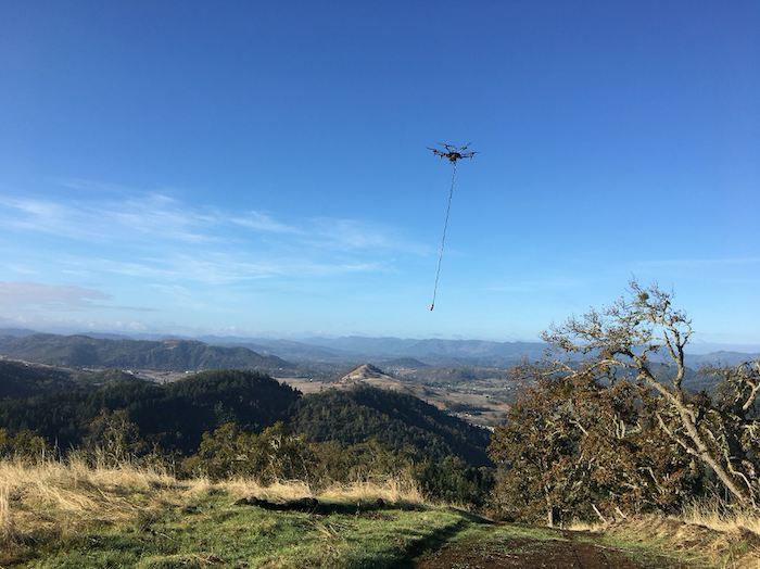
This article is written in partnership with Pioneer Exploration Consultants Ltd. Pioneer employs GEM System’s UAV magnetometer sensor on multiple UAV platforms, such as DJI Matrice 600. The majority of Pioneer’s surveys take place in remote areas throughout Canada, the US, and abroad. These areas are characterized by challenging terrain and harsh environmental conditions. Despite these challenges, Pioneer successfully performs surveys covering thousands of miles each year using UgCS as the mission planning tool.
Content
UAVs equipped with magnetometer sensors represent a technological leap for remote geophysical surveys. They are well-suited for mapping mineral deposits and pipelines, conducting UXO surveys, underground infrastructure, abandoned wells, and other relevant tasks. Many of these missions take place in remote areas with rough terrain, where limited supply and dangerous environments can compromise conventional aerial or ground survey techniques. Magnetometer-equipped UAVs provide increased safety for operations, reduced expenditure, and simplified support and logistics, which greatly benefits both the surveyors and their clients.
When conducting a magnetic survey, UAVs carry magnetometer sensors at very low altitudes – usually 5-50m AGL (Above Ground Level) for mineral exploration and geological surveys, and down to 1m AGL for UXO (UneXploded Ordnance) and underground infrastructure search.
Some manufacturers produce complete magnetometer payloads designed specifically for these kinds of operations, such as the
These three types of magnetometers represent three different designs of magnetometer payloads, all of which require slightly different approaches to mission planning and execution. Common aspects and planning features depending on the type of magnetometer and missions will be covered below.
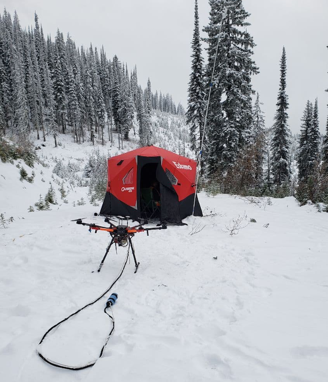
To carry out a successful and safe low altitude magnetic survey mission, one needs to take into account the following factors:
- The precise altitude above ground level and terrain obstacles;
- The pendulum motion of sensors hanging on a tow cable;
- Sensor heading control;
- Special techniques for extremely low-level surveys <5m AGL.
Below you will find a detailed guide on how to plan low altitude magnetic survey missions using UgCS while keeping these issues in mind.
One simple but convenient feature of UgCS is the possibility to create and store multiple missions and routes. You can create an unlimited number of missions, each of which can contain any number of routes.
Firstly, you need to create a new mission:
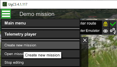
The mission will be assigned an auto-generated name, but later (after first route creation), it is good practice to give meaningful names to your missions – this will allow you to easily find them later:

When you click “Create new mission”, you will be prompted to add the first route to the mission:
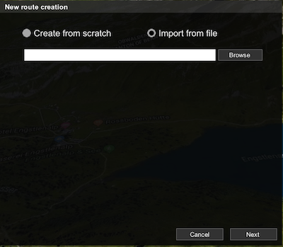
Two options are available:
- ‘Create from scratch’ – select this option to draw your route manually;
- ‘Import from file’ – select this to import a KML file or route file in UgCS format
Customers that request a survey often provide KML files with the boundaries of the survey area.
To import the file, click on the ‘Import from file’ radio button, select the KML file, and click on the ‘Area scan’ radio button:
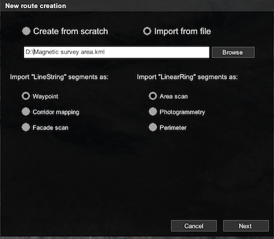
Please note that the KML file must contain ‘LinearRing’ segments in order to import survey area boundaries. To create a ‘LinearRing’ segment in Google Earth, which is the most commonly used tool for this task, you need to click on the ‘Add Polygon’ icon:

Then, the KML file can be imported into UgCS to define the boundaries of the survey mission.
Once the boundaries are defined, select the drone that you will use for your magnetic survey and press ‘Next’:
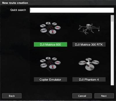
After clicking ‘Next’ a new route based on the imported area will be created.
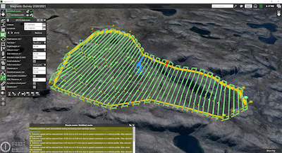
In fact, many route parameters will be derived from previously created ‘Area scan’ routes on the same computer. So, it's a good idea to check route parameters.
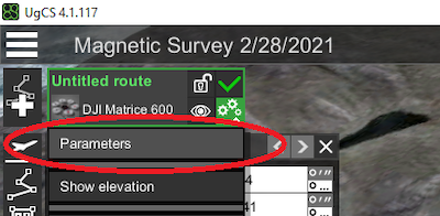
Route and ‘Area scan’ parameters will be reviewed in detail in the next section.
If you want to create a magnetic survey route from scratch, after drone type selection, you will be prompted to set parameters in the route parameters window:
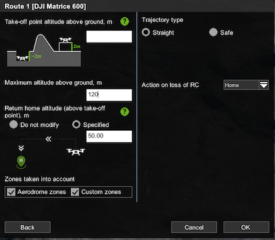
Most parameters in this window are very important for the mission’s safety. Therefore, we shall consider each parameter in detail:
Take-off point altitude above ground. In most cases, this field should be left empty, except in situations like when starting the flight from the roof of a building. In that case, you need to enter the elevation of the actual take-off point above ground level to accurately calculate the altitudes for each waypoint of the route.
Maximum altitude above ground. In most countries, there is a legal limit for the altitude above ground (AGL) for drone flights, unless the operator has special permission. Typically, 120m (or 400ft) is the most common limit. Please don’t set this parameter at higher values without permission from your country’s authorities. This setting can be changed in some instances when the drone has to fly higher than 120m from the home location but not more than 120m above ground level.
Return home altitude. If something goes wrong with the equipment (low battery condition, RC signal loss - depending on drone type and settings), or if the operator presses the ‘Home’ button on the remote controller, the drone will ascend to this altitude before flying back to the home location. One must keep in mind that the return altitude is calculated relative to the home (take-off) position, rather than its current position where the return-to-home sequence was initiated. As a general rule, this parameter’s value should be above the height of the tallest obstacle (including natural obstacles like trees, hills, and rocks) in your survey area.
Trajectory type. For terrain-following missions, this parameter should be set to ‘Straight’. Please note that in this mode your drone will fly between waypoints in a straight line, so the altitude above ground should exceed the height of all trees and other obstacles in your survey area.
Action on the loss of RC. This parameter defines what should happen if the communication link between the ground station (RC remote controller) and your drone is lost. By default (option ‘Home’), the drone will abort the mission, ascend to the Return home altitude and return to the Home location. Another option for this parameter is ‘Continue’. We strongly advise always use the default option (‘Home’). Firstly, in most countries, the law mandates that a permanent communication link should be maintained between the drone and the operator throughout the flight. Secondly, if something goes wrong (really wrong) after the communication link has been lost, you may never find your drone because the ground station will display only its last known position. Naturally, there are some instances in which maintaining a constant radio link is nearly impossible, but overall you should think twice before selecting the ‘Continue’ option.
In addition, please note that if the ‘Continue’ option is selected, the drone will fly to the last waypoint and hover there. If the radio link is lost, the drone will hover until its batteries are drained, at which point it will most probably (depending on the drone’s settings) land at the last waypoint. Consequently, the last waypoint of the route should always be placed near the desired landing point.
Double-check all settings in the route parameters window and press 'OK'.
The next step in the manual route creation process is to click the ‘Area scan’ icon on the left side of the UgCS window.
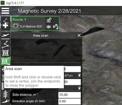
Now, it is possible to set the corners of the survey area by double-clicking on the map with the left mouse button (or by pressing Shift and clicking on the map with the left mouse button).
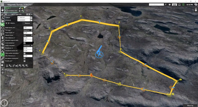
The survey area should be a closed polygon – click on the map with the right mouse button to finish polygon creation. If your customer has provided you with exact coordinates, you can use the ‘Area scan’ inspector to enter (or correct) the coordinates of each point.
After creating a new mission, route, route parameters, and survey area borders (from KML or manually), you need to set main Area scan parameters.
If not all mandatory parameters are set, UgCS will not be able to calculate the route, which will be indicated by a red exclamation mark on the route’s panel.
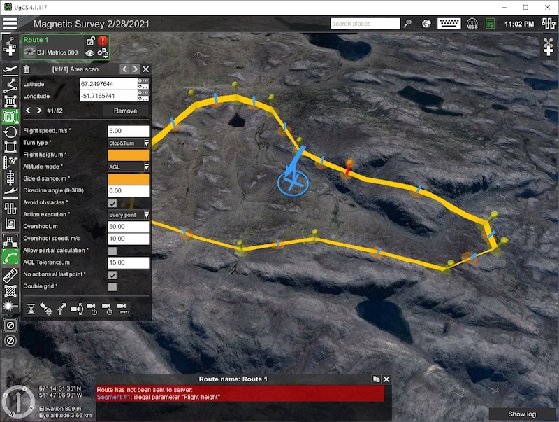
Here you need to specify three mandatory parameters – the flight speed, altitude, and side distance between survey lines.
Flight speed is defined by the survey type (size of anomalies that we need to detect) and the sampling rate of the sensor. Also, in the case of extremely low-altitude surveys, safety considerations can limit maximum reasonable speed. In general, speed can be in the range of 1-10m/s for multirotor drones.
The altitude is defined primarily by the survey type and capabilities of the sensor, or the client’s specific requirements for the purposes of a geophysical survey. For surveys like UXO detection, altitude may be as low as 1m AGL (1m clearance between the sensor and surface), while for mineral prospecting it can be up to 50m and even higher. It is obvious that minimum flight altitude is limited by the presence of obstacles and vegetation/trees on the surface and the capabilities of the drone to maintain precise altitude over the surface.
The distance between survey lines depends on the client’s requirements and the survey type. For magnetic surveys, the distance can be anywhere between 1m and 200m, depending on the purpose of a survey.
Please note that the selection of the speed, altitude, and distance between survey lines for magnetic surveys is outside of the scope of this article.
Once these parameters are set, UgCS will calculate the route and an image resembling the one below should appear on the screen:
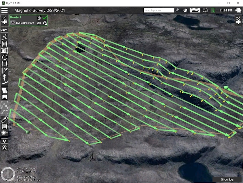
This route can already be used for real flights but is neither optimal nor safe. In the rest of this article, we will explain how to make it much better in both regards.
UgCS allows users to change the direction of survey lines, by entering the value in the ‘Area scan’ inspector, or dragging the blue arrow in the center of ‘Area scan’.
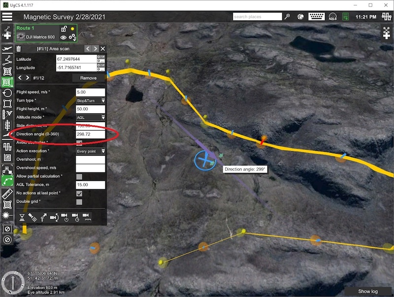
The survey lines can be aligned parallel to the survey area boundaries in order to reduce the duration of the flight and to minimize the number of waypoints and turns. For instance, in the example below we can get a much more optimal route by setting the direction angle to 261 degrees:
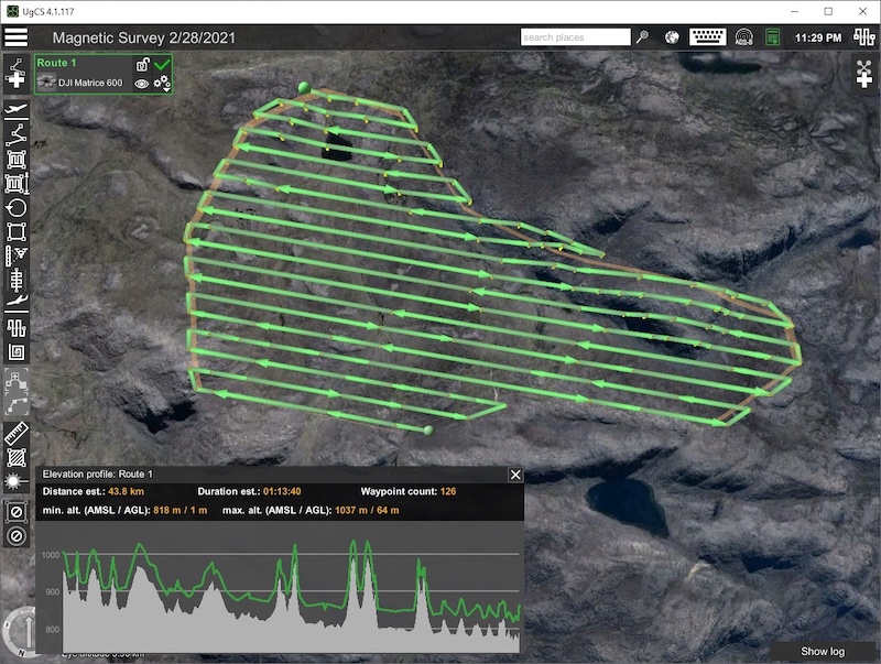
A general rule is that to minimize flight time you need to set the direction of survey lines parallel to the longest side of the ‘Area scan’ boundary.
But the selection of the direction of the survey lines may be a more complex process. In the case of non-convex polygons, you may need to minimize fly-outs outside of the survey area. Also, to gather high-quality magnetic data, you need to choose the direction so that, when on survey lines, the drone will not have to make energetic vertical maneuvers for terrain following. Ideally, when possible, the drone should keep more or less the same absolute altitude on the survey lines. Moreover, for mineral exploration purposes, the line direction would be determined by the exploration manager or geologist on-site and will be independent of survey size or shape.
Most UAVs will fly at the altitude specified in the flight plan, not taking into account the real altitude above terrain features and obstacles.
(Planning for the UAVs equipped by a terrain-following system with radar or laser altimeter will be discussed later).
The mission planning software is to calculates the appropriate altitude at every stage of the flight based on the elevation data in the form of a DEM (digital elevation model).
The DEM elevation data of various geographical locations can be outdated or imprecise. This is particularly true for distant and rural areas, where the majority of magnetic surveys are conducted. The difference in the precision of elevation data is evident in the example below, where data from a popular open-source (SRTM, Figure 16a) and the more reliable Arctic DEM (Figure 16b) were both imported into UgCS.
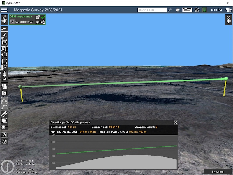
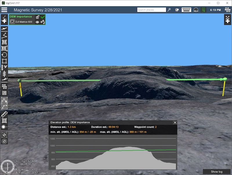
Elevation data imported into UgCS from two different sources:
a) SRTM open source
b) Arctic DEM data
There are many sources of precise DEM data, some of which are freely available, like the ArcticDEM, and some of which are expensive commercial products, like the Airbus WorldDEM.
The image below (Photo 3) shows a typical magnetic survey flight of a UAV (DJI M600) with a magnetometer (GSMP-35U, Gem Systems) managed and controlled by UgCS.
It’s evident from this image that the following factors have to be considered when conducting a magnetic survey with a UAV:
- The required altitude of the sensor above the ground;
- The length of the rope/ tow cable to which the sensor is attached;
- The maximum height of obstacles (e.g. trees) in the survey area.
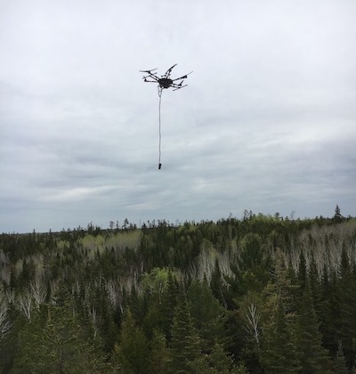
Photo © courtesy: Pioneer Exploration Consultants Ltd.
A parameter that is often overlooked but is crucial for safe mission planning is the maximum barometer drift during flight time. Most drones use barometric altimeters to calculate their own altitude relative to the take-off position. Unfortunately, barometric altimeters invariably have some drift depending on the quality of the sensor, air temperature change, and some other variables. In our experience, the maximum drift for a 30-minute flight can reach up to 5m above or below the true altitude.
The key to selecting a safe altitude for the survey is, therefore, to consider the maximum height of obstacles and add 5m to account for the barometer drift. An additional safety margin may be added depending on the terrain, winds, and some local site issues like the line of sight and your access to the survey area.
There is a special parameter called ‘Safe height over terrain’ in the UgCS vehicle profile, which enables automated height evaluation during mission planning. While the default value is 5m to compensate for the barometer drift, this is not enough for drones with specialized payloads such as a magnetometer on a tow cable. Therefore, for magnetic survey missions, it is necessary to increase the ‘Safe height over terrain’ parameter by the length of the tow cable.
The ‘AGL tolerance’ parameter in the ‘Area scan’ tool allows users to specify how precisely the UAV should follow the desired altitude above ground.
There is a trade-off between following the precise altitude in a certain range and the number of generated waypoints.
The following more precise altitude allows for a safer flight and better quality data. On the other hand, every autopilot has a predefined limit on the number of waypoints that it can handle at once. For example, the DJI M600 drone can only assess 99 waypoints during a single flight.
If a route consists of more than 99 waypoints, intermediate landings are needed to upload the next array of waypoints. (In theory, DJI’s autopilots are able to upload a new route while the aircraft is still in the air, but this operation is less safe and thus should be used with caution.)
For example, if the AGL altitude is set at 40m with a 1m altitude tolerance, UgCS will generate hundreds of waypoints to keep the drone's altitude in the vertical altitude tolerance corridor between 39m and 41m. The smaller the altitude tolerance value, the more waypoints will be generated. Therefore, altitude tolerance must be set to a value that would not lead to exceeding the maximum amount of possible waypoints permission. In the example below, increasing the altitude tolerance from 1m to 10m reduces the number of waypoints from 872 to 364 (Figure 17a and 17b).
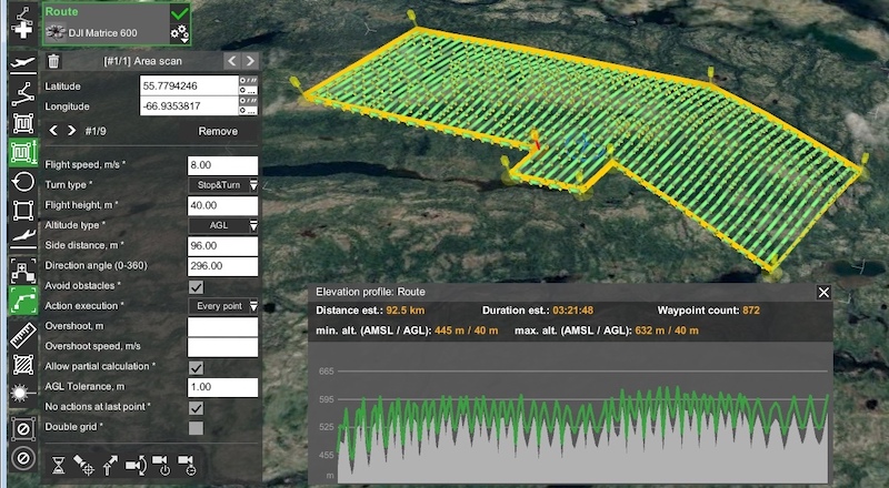
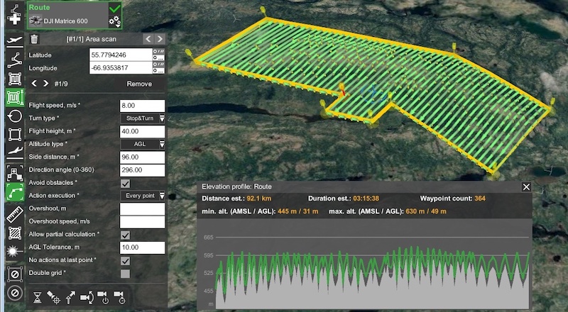
As a result, a mission that employs the DJI M600 UAV with the altitude tolerance set at 1m (Figure 17a) would require nine flights, compared to only four flights for a mission with the altitude tolerance set at 10m (Figure 17b).
UgCS provides an option to upload additional arrays of route waypoints into a drone’s autopilot even while it is in the air. This enables the drone to carry out missions with very high precision, but it is nevertheless advised to keep the number of uploaded waypoints reasonable.
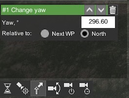
For some surveys, it is important to maintain a constant heading for the UAV (and sensor) during the flight - this can be achieved with the ‘Change yaw’ feature of UgCS (Figure 18).
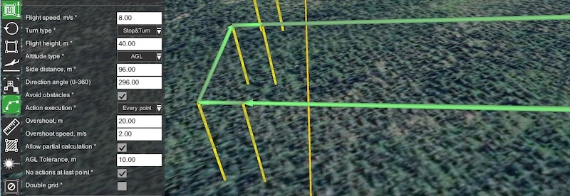
The standard speed for magnetic surveys is 5-10 m/s. A drone entering a U-turn at the end of a survey line at this speed will cause a pendulum motion of the magnetometer on a tow cable. Adding a 20-50m overshoot segment to UgCS’s ‘Area scan’ and reducing the speed to 4-8 m/s for the overshoot segment in combination with the ‘Adaptive Bank Turn’ type will effectively prevent the pendulum motion of the sensor. The shorter the overshoot, the lower should be the reduction in speed. UgCS will add short additional segments to the end of each survey line, but additional waypoints for terrain following will not be added for longer overshoots and between survey lines.
After the initial flight planning, the route can be optimized for a safer flight. This is especially important for magnetic surveys because the survey area can be quite large and may require multiple flights to complete.
Firstly, make sure that the emergency return altitude is set high enough in the route parameters window. This altitude should be high enough to allow a safe way back from any point of the route, taking into account all obstacles and terrain features.
Secondly, the route’s first waypoint should always be set very close to the actual take-off point. This waypoint should be high enough to allow a safe flight towards any other point of the survey mission. This will allow you to set a new starting point (for instance, after a battery swap in the middle of the mission). The drone will ascend to a sufficient altitude set for the first waypoint and then fly straight to the selected “resume point”.
Finally, it is highly recommended to set an additional last waypoint for the route, close to the desired landing point (in most cases, it will be the same as the take-off point). This will ensure a safe return of the drone to the home position, even in situations when there are issues with a handheld remote controller (RC) or a ground station computer, and the drone is configured to continue its mission if the radio link with the ground station is lost.
More detailed information about take-off and landing waypoints is published in the article UgCS Photogrammetry Technique for UAV Land Surveying Missions.
Below we give a few practical recommendations for different types of magnetometers. The same recommendations can be used for other types of devices with similar designs and mounting types.
MagArrow has an aerodynamic shape and, in standard configuration, uses 3m long suspension cords as in Photo 4.
.jpeg)
This configuration helps minimize noise from the drone’s motors and electronics, but has obvious drawbacks - at the end of survey lines in turn points, MagArrow has a tendency for pendulum motion and it is necessary to use quite big overshoots for survey lines to allow MagArrow to stabilize itself in airflow.
Also, if the distance between survey lines is small (1-10m) in combination with high speed after U-turn the sensor will also oscillate in the horizontal plane around the Z-axis.
The consequences of these motions after U-turns are clearly visible in magnetic data and there are no means to fully compensate for them. In the sample in Figure 20, you can see ghost magnetic anomalies after U-turns, they can be easily identified as they have equal distance from the beginning of the survey line.
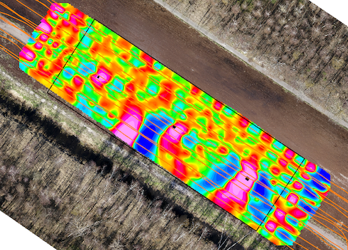
To prevent fluctuations of the sensor, our recommendation is to use overshot segments with the length as [5-10m] * [flight speed], and also specify reduced speed for overshot segments, at least twice slower than the speed on survey lines. For example, for 8m/s the length of overshot segments should be 40-80m for the full stabilization of MagArrow in airflow.
If for some reason you can’t use such long overshot segments, you will have to reduce the speed on survey lines.
The standard method of mounting a MagDrone R3/R4 is on the legs of the drone or right under the hull of the drone.
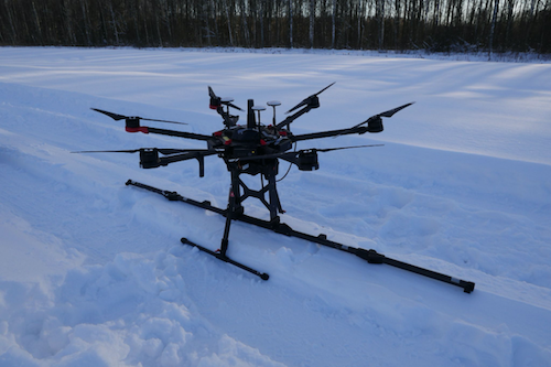
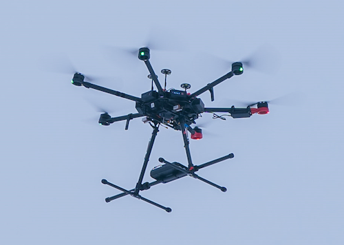
The sensor’s bar should be perpendicular to the direction of flight - the only requirement for the magnetometer orientation. To minimize drone+magnetometer fluctuations after U-turns, it is recommended to have constant drone heading for the entire survey grid.
GSMP magnetometer consists of an electronics box (usually mounted under the hull of the drone) and magnetometer sensor itself, with a cable to be towed under the drone to minimize noise level from the drone’s motors and electronics.
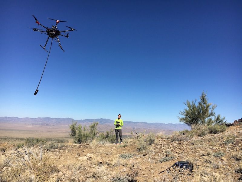
Photo © courtesy: Pioneer Exploration Consultants Ltd.
Recommendations for route planning for the sensor:
- Set constant heading for the entire survey grid.
- Add reasonably overshot for the survey lines (15-20m for flight speed 5-7m or 30-50m for speeds between 8-10m/s). Reduced speed for overshoots is not always needed for longer overshoots, but we recommend an overshoot speed of 4-6 m/s to prevent pendulum motion of the sensor after Uturns.
For some types of surveys (for example, UXO or underground infrastructure detection), it is necessary to have an extremely low altitude sensor over the surface, sometimes <1m.
As the drift of a standard barometric altimeter can be up to 5m during a single flight, it is dangerous to rely on this, even if a very precise DEM was used for mission planning.
For such flights, the use of an active terrain-following system with a radar altimeter is mandatory.
We supply a terrain-following system with a radar altimeter for DJI drones. Discover more.
This system allows flying with the clearance between the surface and sensor starting from a few dozens of centimeters. This makes it possible to gather hi-resolution magnetic data and detect small targets like UXO and pipes/cables.
A magnetic survey mission with a UAV that carries a sensor attached on a tow cable 5m above the ground is very different from a classic photogrammetry mission (when a UAV flies at 100m altitude). Therefore, the magnetic survey’s UAV operator must control the clearance between the magnetometer sensor and the ground and/or obstacles and be ready to take over the control of their UAV with a remote controller.
Taken together, the modern commercial UAV sensors and software allow for a new, effective and economical way to acquire high-quality magnetic survey data. Effective use of these technologies requires training, good knowledge of all components, and very accurate planning. When prepared well, surveyors can greatly benefit from this modern and fast-emerging technology.
Useful links


