The physical principles remain the same whether the GPR is mounted on a drone or operated on the ground.

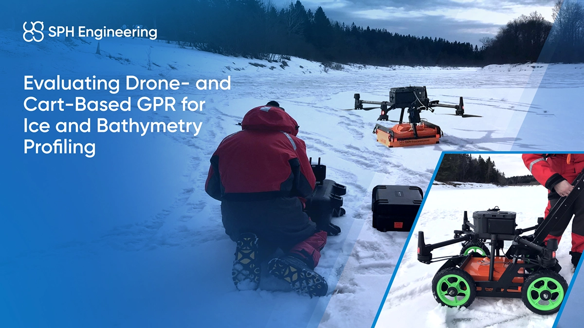
Fig.1 - Drone-Mounted GPR Detecting Underground Anomalies
The depth that can be interpreted from Ground Penetrating Radar data depends on the antenna frequency and the electrical properties of the surveyed material. In UAV applications, penetration typically ranges from a few tens of centimeters to several meters. High-frequency antennas (e.g.,1000 MHz) provide finer detail but shallower reach, while low-frequency systems (50–300 MHz) can detect deeper or larger structures with lower resolution.
Moisture and salinity also strongly affect how deep the radar signal can travel and return useful reflections.
| Antenna / Frequency | Typical penetration from a drone¹ | Approx. smallest target² | Best for (examples) | Recommended altitude | Notes |
| 1000 MHz | 0.3–0.5 m | 5–10 cm | Shallow archaeological features, thin ice/snow layers, near-surface utilities | ≤ 1 m | Highest resolution; most affected by soil moisture; keep AGL low and stable |
| 500-600 MHz | ~1–2 m | 10–20 cm | Ice/snow thickness, shallow void screening, construction site prep | ≤ 1–1.5 m | Balanced depth vs. resolution; good “first-pass” frequency for open-terrain jobs |
| 50–300 MHz (LF) | ~4–30 m + | 30–100 cm | Large voids, thick dry sands, shallow bedrock or geology studies, glaciers profiling | ≤ 2 m | Deepest penetration on the cost of resolution |
¹Typical penetration assumes dry, low-conductivity materials and the listed flight altitude for each frequency.
²Smallest detectable target size is approximate and depends on soil conditions and signal-to-noise ratio.
Estimate expected resolution, detectability of objects, and travel time for soil type and antenna frequency using the GPR calculator.
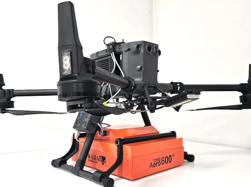
The table provides a summary of what we can expect from the GPR systems available for drone use and their recommended applications. Here, we listed GPR systems manufactured by Radar Systems Inc., Latvia, as this line of GPR covers all possible applications for drone-mounted Ground Penetrating Radars. Any other GPR systems with similar center frequency will have more or less the same practical parameters regarding penetration and resolution.
Please note that penetration and resolution in certain places depend on soil composition, humidity, temperature, etc. In the table below, we used the parameters of a typical “average soil”—some substance with a relative dielectric permittivity of 9, low conductivity, and low water content.
By request, Zond Aero LF GPR systems may come with antennas for custom central frequencies.
| Central frequency, MHz | 1000 | 600 | 500 | 300 | 150 | 100 |
|---|---|---|---|---|---|---|
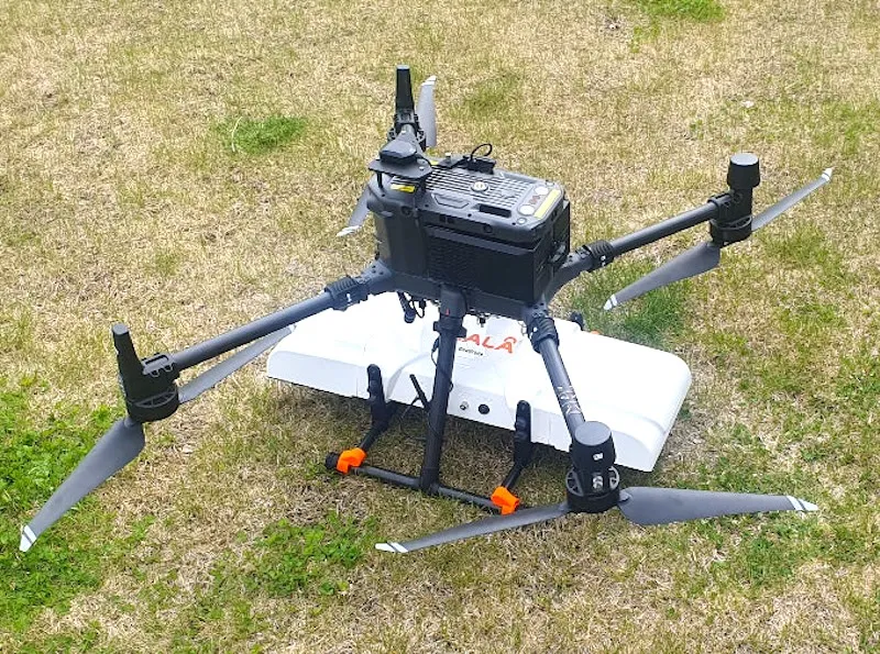
| GPR model | Zond Aero 1000 | Zond Aero 600 & MALÅ GeoDrone 600 | Zond Aero 500 | Zond Aero LF | Zond Aero LF | Zond Aero LF |
| Penetration from surface, m | 0.5 .. 1 | 2 .. 4 | 2 .. 4 | 4 .. 8 | 8 .. 15 | 15 .. 20 |
| Penetration from the drone, m | 0.3 .. 0.5 | 1 .. 2 | 1 .. 2 | 2 .. 4 | 4 .. 8 | 7 .. 10 |
| Penetration from the drone in freshwater, m (water conductivity <200 µS/cm) | - | 0.25 | 0.5 | 2 | 4 | 7 |
| Recommended maximum antenna elevation for airborne survey, m | 0.3 (practical limit is 0.5m) | 0.6 | 0.6 | 1 | 2 | 3 |
| Minimum size of detectable objects under the surface from the recommended altitude, cm | 7 | 10 | 10 | 20 | 35 | 50 |
| Minimum size of “deep” detectable objects from the recommended altitude, cm | 11 at 0.5m | 26 at 2m | 26 at 2m | 50 at 4m | 100 at 8m | 180 at 15m |
| Minimum diameter of detectable linear non-conductive objects like an empty plastic pipe, cm | 5 | 10 | 10 | 17 | 33 | 50 |
| Minimum diameter of detectable linear conductive objects like a metal pipe or a water-filled plastic pipe, cm | 5 | 8 | 8 | 13 | 27 | 40 |
| Applications | ||||||
| Small object search |  | | | |||
| Glaciology, snow/ice thickness profiling | | | | | | |
| Geological stratigraphy • subsurface stratigraphy • structure • bedrock surface | | | | | | |
| Geotechnical surveys • cavity search • sinkhole search | | | | | | |
| Utility Search • cables • water & sewage pipes • gas pipes • oil pipes | | | | | ||
| Underground infrastructure mapping | | | | | ||
| Archaeology • artifacts • hidden structures • stratigraphy • foundations | | | | | ||
| Archaeology • caves • tombs • tunnels | | | | |||
| Forensics archaeology | | | | | ||
| Freshwater Bathymetry | | | | |||
| Mining & Quarrying • rocks • fractures • faults • joints | | | |
When selecting the most suitable GPR survey method, one of the key decisions is whether to use an airborne (drone-based) or terrestrial (ground-based) survey setup. The choice depends on factors such as terrain accessibility, required resolution, target depth, and survey area size.
There are several standard methods for conducting GPR surveys, each with its own benefits and drawbacks. No single method is universally applicable; the appropriate or most suitable approach should be chosen based on the survey target and environmental conditions. Below is a review of the most popular methods.
Radar Systems Zond Aero GPR systems are designed to be fully versatile and support the most optimal survey method for a particular job or project. That means that by investing once in the GPR system, customers can use the same GPR in the most efficient way.
Most traditional and common method for GPR scans, especially on paved roads or any hard surfaces.
+ Simple and well-known method
+ Suitable for confined spaces on streets of towns and similar environment
+ Allows “real-time” data interpretation to mark detected anomalies on surface
- Not suitable for soft or sticky surfaces where use of wheeled carts is complicated
- Limited productivity, survey speed is <1m/s
One more traditional method. Can be used in situations when load-bearing capacity of the ground surface is not suitable for a wheeled cart. Applicability of the method is restricted by accessibility of survey area by feets.
+ Simple and well-known method
+ Suitable for confined species where no other methods work, for example in a forest
+ Allows “real-time” data interpretation to mark detected anomalies on surface
- Not suitable for too soft or sticky surfaces where operator can’t walk without excess efforts
- Data quality is subject of possibility to walk having stable GPR antenna orientation
- Limited productivity, survey speed is <1m/s
- Can be physically challenging as the operator carries all the equipment
Zond Aero 500 NG and Zond Aero 1000 NG come in the box with an integrated battery and WiFi router as a standard. GPR can be connected to a battery and WiFi router, making it possible to conduct surveys towing the box behind the operator. This method is suitable for more or less even surfaces where it is not possible to use wheeled carts (over snow, sand, soft soils) but still accessible by feet.
+ Simple method
+ Allows “real-time” data interpretation to mark detected anomalies on the surface
- Not suitable for too soft or sticky surfaces where the operator can’t walk without excess efforts
- Suitable for more or less even surfaces only
- Very limited productivity, survey speed is <0.5m/s
- Can be physically challenging
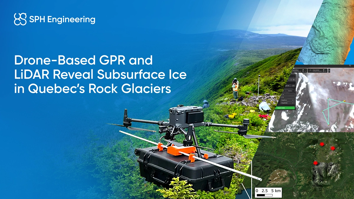
Drone-mounted GPR implements the motto “safer, cheaper, faster”.
+ The only way to do the job without entering the survey area
+ Suitable for areas with safety or health risks for the operator (glaciers with crevices, contaminated soils, etc.)
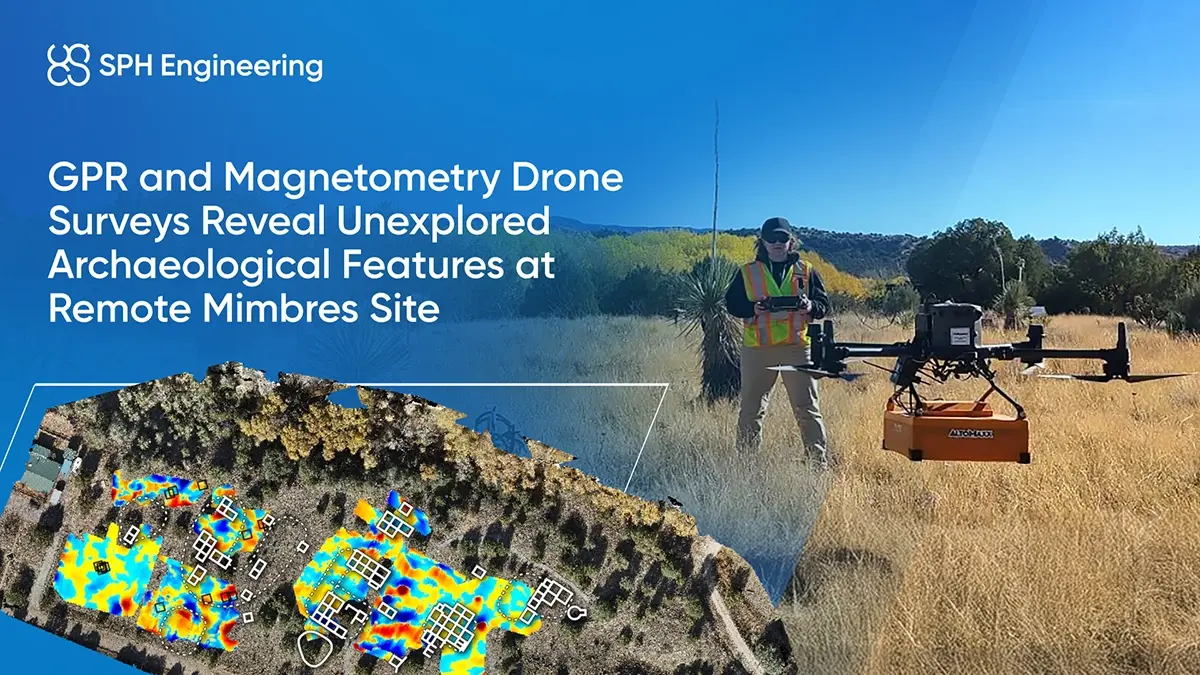
+ Extremely high productivity over large unobstructed areas where the productivity of terrestrial surveys will not be economically reasonable (for example, scanning huge fields for solar panel farms for the depth of bedrock and presence of rocks)
+ Suitable for rough terrain where terrestrial surveys may be impossible (ice and snow-covered ground, rocky and uneven terrain, across rivers, and in avalanche-prone areas)
+ Very precise automatic following of pre-programmed survey lines
- Requires additional sophisticated equipment: drone equipped with terrain following system plus flight planning and control software
- Not suitable for confined spaces (streets, etc.)
- Not suitable for areas with tall vegetation (all other methods may also be unsuitable without land preparation)
All GPR systems use the same principles but vary in application due to different antenna frequencies:
The antenna design reflects:
The variety of GPR's ensures the right system for every subsurface investigation needs.
These are the tips for effectively utilizing the GPR system. This is not an exhaustive list, and we are always ready to discuss your specific solution in detail.


The GPR calculator can be used to estimate the detectability of targets at a particular depth and flight altitude (antenna elevation).
Enter information about Antenna Elevation, type of GPR system, Estimated Target Depth, and Material/Soil type to get the results.
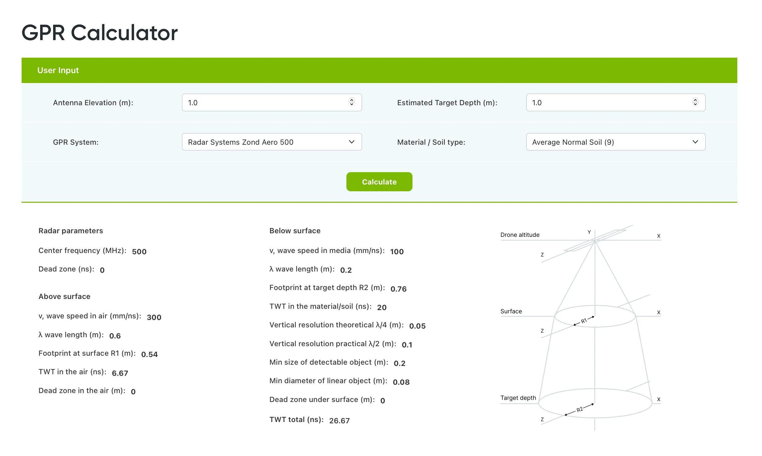
Fig.7 - GPR calculator by SPH Engineering
Share details about your survey area and objectives, and we’ll recommend the most effective drone-based GPR solution for your application.
Unsure? Try the GPR Calculator first.
The GPR system for UAVs consists of multiple components: GPR, SkyHub, laser/radar altimeter, UgCS and data processing software. Discover the components of airborne GPR system, training and certification on SPH Engineering's shop »»»
Compatible drones: DJI M400/M350/M300/M600, Inspired Flight IF1200A, Harris Aerial H6, and Wispr Ranger Pro and similar UAV


GPR data comes from the sensor in digital form and is not meant for direct human interpretation, unlike photos from cameras. It requires specialized software for processing and interpretation.
These methods of GPR data representation are the most popular, but many additional options exist, including export into formats that can be imported into CAD and GIS systems.

Fig.2 - GPR profile crossing a gas pipeline with interpretation. Data was collected using the Zond Aero 500 GPR system, processed, and interpreted in Radar Systems Prism2 software
The results of GPR surveys can be presented in different forms. The most common and “natural” format for GPR data is a “profile” - a vertical slice of data along the survey line.

Fig.3 - Horizontal slice of the subsurface to visualize the path of utilities. Data was collected using the Zond Aero 500 GPR system and processed in Geolitix
Another popular form is horizontal slices, as they give a better understanding of where the detected objects are under the surface and about the shape of objects.

Fig.4 - 3D representation of the same utilities as on the image with horizontal slices. Screenshot of Geolitix
Many customers prefer to see 3D reconstructions of the underground world - and that is also possible. It will require more processing and preparation steps, but as this method gives maximum understanding in complex situations, it becomes more and more popular, thanks to modern GPR processing software radically simplifying that task.

Fig.5 - Ice thickness grid. Data was collected using the Zond Aero 1000 GPR system and processed in Geolitix
One more popular method is to generate thickness grids, for example, to answer questions like “How thick is the sand layer covering bedrock” or “How thick is the ice”.